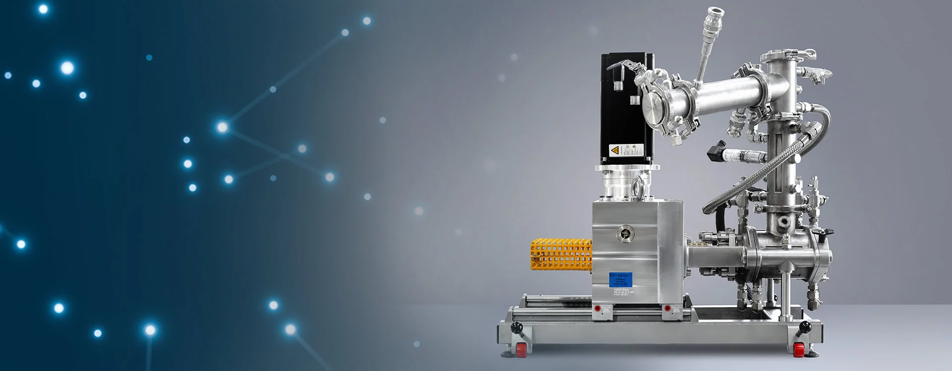
Lab Kneader Research and development platform for high-viscosity liquids

The LIST LLK 1.0 kneader is arriving at the lab

High viscosity processing is challenging. Laboratory capabilities are limited. Development takes time. Time is not available. Project risks increase. Up to now.

Benefits

  • Unlock lab scale viscosity limitations

  • Prepared for conti processing

  • Product and processing differentiation

  • Save development time

  • Reduce development risk

LLK 1.0 – Summary

Industrial success factor downscaled to lab

The LIST Lab Kneader LLK 1.0 brings LIST’s scalable industrial high viscosity processing technology to laboratory scale.

Step in the lab

The LLK 1.0 is designed to fit in your fume hood for your first experiments without the usual viscosity limitations.

Mission

The LLK 1.0 shall ensure that no process idea misses industrial application due to viscosity limitations at lab scale.

Pushing the processing limits of R&D

The LLK 1.0 is your tool to develop products in the laboratory with a technology which is scalable to modern, efficient, sustainable, and continuous industrial processes.

Reduce risk and save time

The LLK 1.0 avoids a processing technology switch at a later point. This reduces development risk and saves time to market.

Prepared for continuous processing

The LLK 1.0’s kneading shaft design follows industrial concepts for scale-up consistency.

Features

A wide range of processing low and highly viscous materials with difficult rheological behavior: sticky, pasty, viscous, crust-forming.

The reactor can be operated from vacuum at 1 mbara to pressure up to 10 barg.

The mixing kneading shafts can be equipped with an electric heating cartridge to maximize heat input and preclude a cold sink.

Safe handling of product phase changes which may typically occur during processes such as evaporations, drying, devolatilizations, crystallizations, (de)sublimations, polymerizations, polycondensations, chemical solid-liquid and solid-gas reactions, recycling and recovery.

A top sight glass allows the operator to observe the product by eye or through a camera (not included) with a reflection free illumination for best view into the process chamber.

The shafts are sealed with a two-stage stuffing box and an additional rotary seal. A first stages close to the reaction chamber prevents the product from leaking out, a second stage allows for a gas-tightness reaching vacuum levels down to 1 mbara.

The complete assembly as shown here is designed to fit in a typical fume hood by requiring a footprint of 710 mm x 450 mm, and 720/750 mm in height, and can be placed on a typical lab bench: 80 kg.

The mixing kneading shafts rotate from 10 to 100rpm. The system is designed for high torques up to 80Nm. This allows to introduce a large specific torque into the product and to process highly viscous media of up to 20’000 of Pas shear viscosity.

Laboratory standard glass condensers. Optionally, metal condensers are available.

Same mixing kneading shaft design like industrial LIST KneaderReactors, which usually operate in a continuous mode for very high capacities and very low fluctuations. Thus, the switch to a continuous process is prepared.

The mixing kneading shafts are designed for full self-cleaning of all product-wetted housing and shaft surfaces. This enables forced homogenization of difficult-to-handle, viscous, sticky and crust-forming materials during unlimited residence times.

A dome allows for extra space necessary e.g. for evaporation processes where small liquid volumes expand to large gas volumes.

The process chamber process contains 1 litre. Usually, a kneader is operated with a filling grade in between 50-75%. Therefore, 500-750ml effective product volume allow for a time efficient and cost sensitive development of high value products.

Two different machine types are available. Both with a kneading shaft geometry identical to industrial applications. No need to change the processing approach for larger scales. This saves time to market.

The handles and rolls allow an easy handling under the fume hood, by tilting and rolling only a fraction of the full weight.

The feed product can be dosed through the top of the Dome or through several side plugs in the dome.
It can be solid, liquid or gaseous.

The casing, front & end plate and dome are jacketed for heating or cooling with a liquid thermal oil by a heating unit.

The dome and all the gas-space parts can be easily dismantled through tri-clamp connectors. The front and end plate are easily removable. Also, the shafts can be removed by the operator with extra tools that are included in the scope of supply.

Liquid product can be drained through ports in the front plate. For the discharge of viscous or solid product, either the whole front plate can be removed, or the shafts can be pulled out of the casing by sliding the gear-motor-block back on rails.

Specifications

Would you like to learn more about the technology?